For the past couple of months I’ve been playing around with a personal project to write images to our shop’s vinyl cutter. Recently Travis discovered that if a very large image is sent to the cutter all at once, it will cause a serial buffer overflow and crash the knife.
The natural reaction is to enable flow control (page 15) on the serial device, such that the vinyl cutter can step back from the brink if the buffer fills up. But that doesn’t seem to work for whatever reason — I suspect that my shoddy USB to serial adapter doesn’t support it.
So I made a feature that will take the movement speed of the vinyl cutter, estimate the duration of each line segment’s execution, and then send the serial as smaller chunks in intervals. This does work, but we noticed that the time calculated doesn’t match up with the time it actually takes the vinyl cutter to route a shape. Sometimes it’s off target by up to half a minute… What’s up with that?
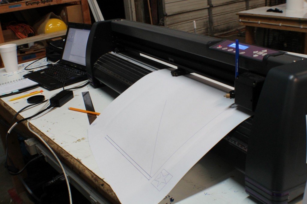
I had some suspicions, and set to work measuring the travel time of the cutter and comparing it to the speed reported by the cutter’s settings. The setup was pretty straightforward; I mounted a pen in place of the knife, loaded a large sheet of paper, and marked out endpoints of 250mm from the origin along X, Y, and diagonal.
First we cover some basic observations:
– The cutter has two speed settings, one for cut and one for travel (buried in a menu).
– The speed is applied to each axis individually. Diagonal cuts are faster by d^2 = x^2 + y^2.
– The speed is the same for X and Y axis travel.
– The speed is unaffected by the cut pressure (downforce setting in grams).
To run the tests I used a stopwatch and a hand written .hpgl file:
IN;SP1;

PU0,0;

PD0,10000;

SP0;IN;
The important line is ‘PD0,10000;’ which tells the cutter to travel 250mm along the Y axis, since one of HP’s graphics units is 0.025mm. This line was replaced with ‘PD10000,0;’ and ‘PD7071,7071;’ to test the X axis and diagonal.
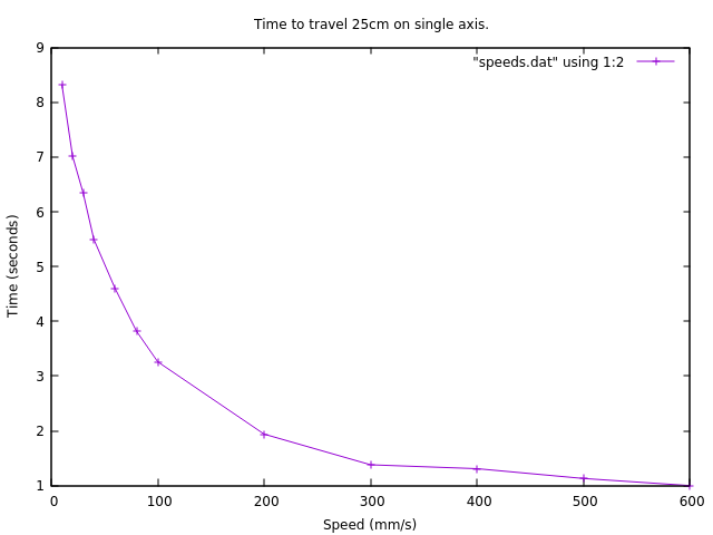
So I ticked through about a dozen speed settings and timed the travel of the PD command three times each, and averaged the results.
| Speed (mm/s) | Time (s) |
| 10 | 8.32 |
| 20 | 7.02 |
| 30 | 6.34 |
| 40 | 5.50 |
| 60 | 4.60 |
| 80 | 3.82 |
| 100 | 3.26 |
| 200 | 1.94 |
| 300 | 1.38 |
| 400 | 1.31 |
| 500 | 1.13 |
| 600 | 1.00 |
Plotted with gnuplot:
And then adjusted to show the measured speed:
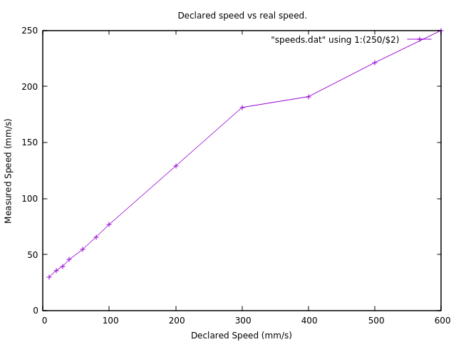
That’s pretty encouraging. It looks like the relationship is very linear all the way up to 300mm/s. While the vinyl cutter will accept up to 1000mm/s as the settings input, I feel like 300mm/s is a pretty good cap, since we usually cut around the 100-200mm/s range.
This section, 10 to 300, is so straight that I didn’t even bother with linear regression or anything, and instead opted to use point-slope to find the relationship:
(181mm/s - 30mm/s) / (300mm - 10mm)
= (151mm/s) / (290mm)
= ~0.52(1/s)
(y - 30) = 0.52(x - 10)
y - 30 = 0.52x - 5.2
y = 0.52x + 24.8
The results? Worse than I hoped, but better than I expected. It turns out the motion is a lot more complex than this, and this new function which translates the reported speed to real speed only vaguely represents what’s really going on. For instance, small cuts will be off by up to 2 seconds… on the fast side! And curves behave differently as well, which is odd considering that the HPGL we’re using creates curves exclusively with line segments…
Anyway, the end result is the same, our vinyl cutter software can now accept very large files!
Greetings!
I have a similar vinyl plotter that I am donating to a makerspace in Birmingham. I don’t have software. What software do you use? It originally came with some free software but that was 10 years ago and it is probably out of date now.
Thanks,
Wesley
Hi Wesley,
Some of our members use Sign Blazer, which works OK but has limitations and eccentricities.
I’m currently trying to make our own replacement software, called localplot. It’s still in a pretty basic state, but I have an Archlinux AUR package and I’d be glad to look into packaging it as a .deb if that would be helpful.
Thanks for the quick reply.
The plotter is a model MH721. It looks like the one you have. I found a software package for $59 called VinylMaster Cut that looks like one option. I am delivering the plotter this week and they may be in touch with you about your software as well. Thanks for offering to assist.
Have a great day,
Wesley
On a different note. When I was at your location I noticed you have a laser plotter/cutter. With one of those can you engrave a jpeg image on a sheet of 2 color laminate to create a panel front? Like a red panel with white letters but from a jpeg file?
Thanks,
Wesley
Should be possible, people have done similar things with the laser before. That job sounds like it might be better suited for the CNC mill though 😛
“Crash the Knife” will be the name of my new punk-rock cover band.